
- Pspice schematics version 9.1 software update#
- Pspice schematics version 9.1 software full#
- Pspice schematics version 9.1 software download#
It also provides digital worst-case timing analysis to help find timing problems during signal transitions. Its simulation provides dc, ac, and transient analysis. OrCAD PSpice handles more than just bias calculations, of course.

There are also a number of tutorials available for the program:
Pspice schematics version 9.1 software update#
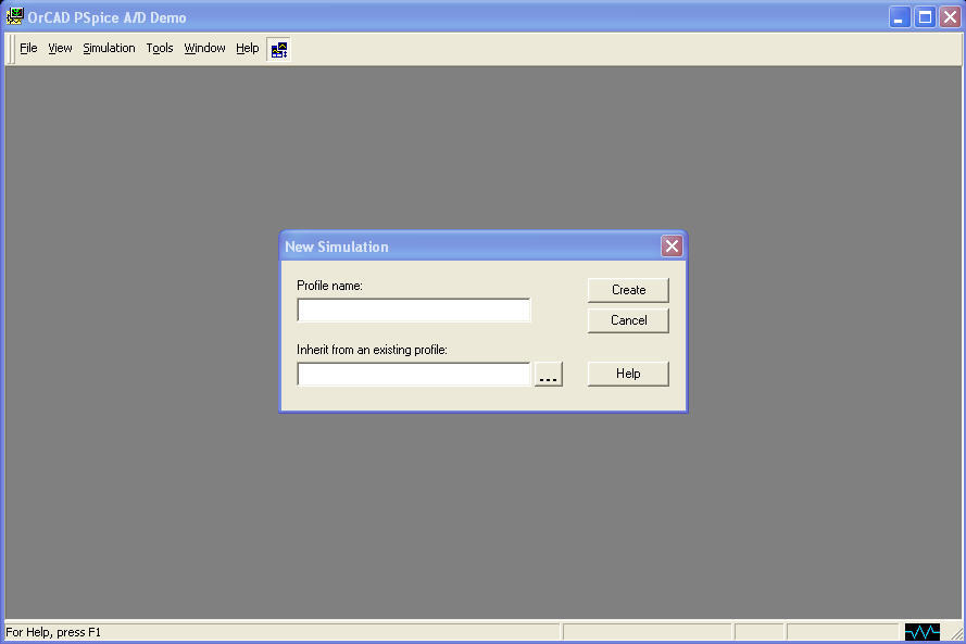
PSPICE 9.1 Student Version from Orcad includes limited versions of PSpice A/D 9.1, Web Update 1, including PSpice Schematics 9.1 a choice of schematic editors, PSpice Schematics 9.1, Capture 9.1, and a part database from Digikey. A screen grab from the Orcad PSpice program. Here are a few inexpensive and widely used programs that fit the bill. These days, it’s often preferable to use a simulation program to determine circuit biasing for all but the simplest cases. Positive bias pulls electrons away from the junction so that it cannot conduct.īias, in this case, high-frequency, is used in magnetic tape recording to improve audio quality by removing objectionable hiss. When negative bias is applied, electrons are repelled, gathering as charge carriers at the N-P or P-N junction. Besides being applied within an amplifier so it operates within a predetermined part of its transconductance curve, negative bias may be applied to a cathode so that electrons are launched and subsequently accelerated toward a CRT screen.īiasing plays an important role in the operation of a diode and in transistors where any two terminals constitute a virtual diode. Most often, this force is unchanging in amplitude and polarity. It can be magnetic, mechanical, hydraulic, pneumatic – wherever force is introduced into a system. In both cases, clipping of the reproduced signal will occur.īiasing can take forms other than electrical. Otherwise, the input signal to be reproduced may drive the device beyond cutoff, or it may be insufficient to put the device fully into its linear region. dc bias, the purpose of which is to keep the device in its linear operating range.
Pspice schematics version 9.1 software download#
Download the PSpice design and simulation suite today to start your design.If a semiconductor or vacuum tube is to accurately reproduce or amplify signals on its input, it must have on its input a non-time-varying dc voltage, i.e. Available at no cost, it is easy to get started. Using PSpice for TI, you have access to tools to address your simulation needs as you progress through the design cycle, from circuit exploration to design development and verification. After you have verified that you have the correct device for your application, you can access the TI store to purchase the product.
Pspice schematics version 9.1 software full#
In addition to a full library of preloaded models, you can easily access the latest technical collateral for TI devices within the PSPICE-FOR-TI tool. You can also run co-simulation of multiple TI devices to better represent your system. Within the PSpice for TI design and simulation tool, you can search for TI devices, explore the portfolio, open test benches and simulate your design to further analyze the selected device.

Create complete end equipment designs and prototype your solutions before you commit to layout and fabrication, reducing time to market and development cost. The PSpice for TI design and simulation environment allows you to simulate complex mixed-signal designs with its built-in library.

Available at no cost, PSpice for TI includes one of the largest model libraries in the industry, spanning our analog and power portfolio, as well as select analog behavioral models. This full-featured, design and simulation suite uses an analog analysis engine from Cadence®. PSpice® for TI is a design and simulation environment that helps evaluate functionality of analog circuits.


 0 kommentar(er)
